Filters
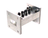
C-Band Altimeter Radar Elimination Filter
This uniquely designed low-loss, weather-proved lightweight filter provides
suppression of marine and altimeter signal in C-Band.
Due to a very low group delay variation, this filter is ideal for digital satellite
transmission. Customer-defined pass-band as well as stop-band rejection up to 75dB is available.
The filter shown bellow is 7 poles made from aliminum, silver-plated, weather proved
and painted over for reliable outdoor applications.
| Parameter Name |
Specifications |
 Datasheet Datasheet
|
| Pass-Band |
3.70 - 4.20 GHz |
 |
| Pass-Band Insertion Loss @ 3.7 - 4.1 GHz |
<0.10 dB maximum |
| Pass-Band Insertion Loss @ 4.2 GHz |
<0.15 dB maximum |
| Pass-Band Return Loss |
>1:1.15 (23 dB) maximum |
| Pass Band Group Delay Variations |
2.5 ns over any 36MHz |
| Stop-Band |
4.25 - 4.40 GHz |
| Stop Band Rejection |
55 dB minimum |
| Interface |
WR229 with CPR229G flanges |
Dimensions |
8"x5.8"x3.88" |
Weight |
3 lbs |
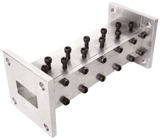
C-Band Interference Suppression Filter
These low loss, light and robust C-Band band-pass filters had been designed specifically
to efficiently suppress strong out of band interference,
caused by navigational communications (radar), as well as many types of other
terrestrial interference, providing strong rejection of unwanted spurious spectrum below
and above the pass-band frequency range from DC to lower Ku-band.
These filters also practically eliminate transmit (uplink) band frequencies so a separate band pass filter
is not needed.
| Parameter Name |
Specifications |
Datasheet
|
| Pass-Band |
3.70 - 4.20 GHz |
 |
| Pass-Band Insertion Loss @ center frequency |
<0.4 dB maximum |
| Pass-Band Insertion Loss @ band edge |
<0.9 dB maximum |
| Pass-Band Return Loss |
>1.25:1 maximum |
| Pass Band Group Delay Variations |
7.5 ns |
| Rejection |
| At 3.665 / 4.235 GHz |
10 dB |
| At 3.651 / 4.250 GHz |
20 dB |
| At 3.636 / 4.267 GHz |
30 dB |
| At 3.617 / 4.285 GHz |
40 dB |
| At 3.593 / 4.307 GHz |
50 dB |
| At 3.564 / 4.329 GHz |
60 dB |
| At 3.533 / 4.353 GHz |
70 dB |
| At 3.485 / 4.380 GHz |
80 dB |
| Below 3.485 GHz |
more then 80 dB |
| From 4.380 to 11.130 GHz |
more then 80 dB |
| Interface |
WR229 with CPR229G flanges |
Dimensions |
5.35" x 3.88"x 2.75" |
Weight |
3 lbs |
Ridged Evanscent - mode filters
These low-loss, low power, miniature evanescent-mode band-pass
or harmonic filters could be used in applications
where filter size and weight are critical,
primarily for Ku-Band (up to 20GHz) frequencies and bellow.
The filter shown bellow is a 9-poles ridged evenescent-mode filter with direct transforming
via resonant windows. Shorter and ligher than conventional filters of this type.
| Parameter Name |
Specifications |
|
| Pass-Band |
14.46- 14.9 GHz, Tunable |
 |
| Insertion Loss |
0.16 dB |
| Return Loss |
25 dB |
| Rejection,Tunable |
50 dB at 16.226 GHz |
|
70 dB at 16.6 GHz |
|
> 60 dB at 17GHz to 45GHz |
| Multipaction Power, Watt |
N/A |
| Dimensions, mm |
50.7x38x38 |
| Weight, grams |
50 |
Waveguide Band-Pass Cavity Filters
These high-Q, high-power, low-loss filters find numerous applications
ranging from wide bandpass filters, up to 20% of the central frequency,
to ultra-narrow, less then 1% (notch) filters.
These filters are manufactured from aluminum, silver plated.
Temperature stable versions, using more stable materials are available.
Choice of customer - defined waveguide flanges (choke, cover, hermetic).
Optional coaxial interface, customer-defined or standard.
The filter shown bellow is WR62 band-pass cavity filter.
| Parameter Name |
Specifications |
|
| Pass-Band |
14.700 - 15.250 GHz |
 |
| Pass-BandInsertion Loss |
0.3 dB maximum |
| Pass-Band Return Loss |
24 dB minimum |
| Rejection |
90 dB minimum at F > 13.700 GHz |
|
70 dB minimum at 13.70 - 14.00 GHz |
|
20 dB minimum at 14.0 GHz to 14.5GHz |
|
20 dB minimum at 14.45 - 16.30 GHz |
|
70 dB minimum at 16.3 - 21.00 GHz |
| Power, peak |
2KW |
| Dimensions, mm |
92x33x33 |
| Weight, grams |
58 |
Harmonic Rejection Filters
These heavy-duty, Ultra High Power (up to 10% of appropriate waveguide power handling),
low insertion loss, sharp roll-off filters with compact size and llightweight
could be an ideal solution in many applications. Two Ku-Band harmonic regection filters
are shown bellow.
WR75 Ku-Band Second and Third Harmonic Regection Filter
| Parameter Name |
Specifications |
|
| Pass-Band |
13.75 - 14.50 GHz, Tunable |
|
| Pass-BandInsertion Loss |
<0.2 dB |
| Pass-Band Return Loss |
<25 dB |
| Rejection of: |
|
| Second Harmonic |
>80 dB from 27.5 - 29.0 GHz |
| Third Harmonic |
> 60 dB from 41.25GHz to 43.5GHz |
| Dimensions,inch |
1.5x1.5x3.5. max, flanges included |
| Interface |
WR75 |
WR75 Ku-Band Second Harmonic Filter
| Parameter Name |
Specifications |
|
| Pass-Band |
13.75 - 14.50 GHz, Tunable |
|
| Pass-BandInsertion Loss |
<0.1 dB |
| Pass-Band Return Loss |
<25 dB |
| Rejection of: |
|
| Second Harmonic |
>60 dB from 27.5 - 29.0 GHz |
| Dimensions,inch |
1.5x1.5x3.5. max, flanges included |
| Interface |
WR75 |
|
